
Sensor Function Adaptation and Debugging for the Hi3093 Development Board (openubmc.cn)
实践案例
2025/08/25郭馨
Sensor Function Adaptation and Debugging for the Hi3093 Development Board (openubmc.cn)
Introduction
This article describes the common debugging and adaptation methods for adapting I2C sensors based on the MYC-LHi3093 development board.
Material Preparation
- Hi3093 core board
- Power adapter of the core board
- Network cable
- Type-C USB cable
- Jumper wires
- Expansion board (with the LM75 sensor)
I2C Tool Application
Currently, openUBMC 2506 version does not support I2C tools to perform i2cdetect and i2ctransfer operations. This article references the post Self-made I2C Debugging Tool (i2cdetect and i2ctransfer for openUBMC) and uploads i2cdetect and i2ctransfer to the /data directory using SCP.
Sensor Debugging
According to the hardware schematic diagram of the development board, connect the BMC I2C bus through pin headers on the development board to the external debugging board through jumper wires. The following figure shows the connections of the power supply, GND, SDA, and SCL on I2C9.
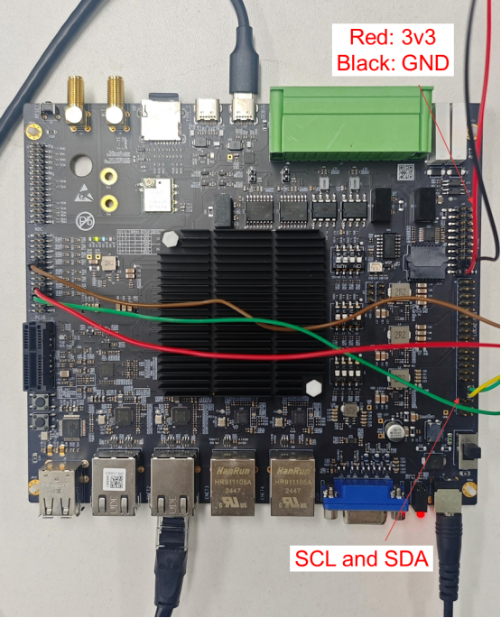
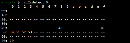
It is known that I2C9 is mounted with LM75(0x48), LM75(0x4f), and PCA9546(0x70), and PCA9546 channel0 is connected to LM75(0x49). Run the ./i2cdetect 9 command in the /data directory. It shows that preceding devices have been detected correctly.
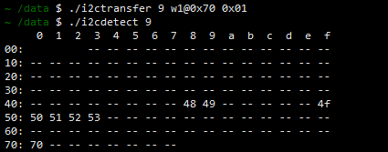
Run the ./i2ctransfer 9 w2@0x70 0x01 command to enable PCA9546 channel0. Then run the ./i2cdetect 9 command. LM75(0x49) can be detected now.
The lower four bits of the PCA9546 control register correspond to four channels. You can use i2ctransfer to enable a specified channel and check whether the I2C device connected to the channel is normal.
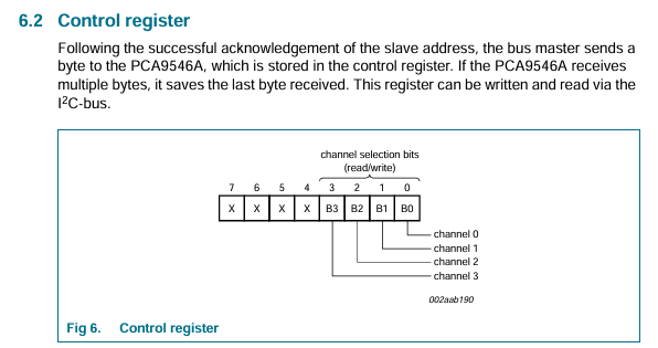
You can run the following commands to enable the four channels of PCA9546 independently. Writing 0x00 to PCA9546 can disable all channels.
| Channel ID | Command |
|---|---|
| Channel 0 | i2ctransfer <i2cbus> w1@0x70 0x01 |
| Channel 1 | i2ctransfer <i2cbus> w1@0x70 0x02 |
| Channel 2 | i2ctransfer <i2cbus> w1@0x70 0x04 |
| Channel 3 | i2ctransfer <i2cbus> w1@0x70 0x08 |
Sensor Configuration
The following uses the board name openUBMC as an example. Configure the vpd/vendor/Huawei/Server/Kunpeng/openUBMC/root.sr file as follows:
- Add I2c_9 to ManagementTopology > Anchor > Buses.
- Add the LM75 sensor chip and Connectors configuration under I2c_9. Within the Connector section, configure Connector_DemoCard to indicate that PCA9546 is located in the CSR of the downstream component DemoCard.
- Under Objects, configure the LM75 object, Entity, and ThresholdSensor. Since this sensor obtains values through periodic polling, Scanner must also be configured.
- Also under Objects, configure Connector_DemoCard. An IdentifyMode value of 2 indicates that the downstream component is not a Tianchi component. Non-Tianchi components utilize three configuration items (Bom, Id, and AuxID) to determine the downstream component CSR name, which is formatted as: Bom_Id_AuxId.csr. In this example, the downstream component CSR name is 14100513_DemoCard_0.sr. The I2c_9 configuration within Buses indicates that the bus connecting to the downstream board is I2C9. Note that Position of any two connectors within the same CSR file cannot be duplicated.
{
    "ManagementTopology": {
        "Anchor": {
            "Buses": [
                "I2c_1",
                "I2c_2",
                "I2c_3",
                "I2c_4",
                "I2c_5",
                "I2c_6",
                "I2c_7",
                "I2c_8",
                "I2c_9",
                "I2c_11"
            ]
        },
        "I2c_9": {
            "Chips": [
                "Lm75_1",
                "Lm75_2"
            ],
            "Connectors": [
                "Connector_DemoCard"
            ]
       }
    },
    "Objects": {
        "I2c_9": {
            "Id": 9
        },
        "Lm75_1": {
            "OffsetWidth": 1,
            "AddrWidth": 1,
            "Address": 144
        },
        "Lm75_2": {
            "OffsetWidth": 1,
            "AddrWidth": 1,
            "Address": 158
        },
        "Scanner_InletLM75": {
            "Chip": "#/Lm75_1",
            "Size": 1,
            "Offset": 0,
            "Mask": 255,
            "Period": 1000
        },
        "Scanner_OutletLM75": {
            "Chip": "#/Lm75_2",
            "Size": 1,
            "Offset": 0,
            "Mask": 255,
            "Period": 1000
        },
        "ThresholdSensor_InletTemp": {
            "AssertMask": 516,
            "DeassertMask": 516,
            "ReadingMask": 4626,
            "Linearization": 0,
            "M": 100,
            "RBExp": 224,
            "UpperCritical": 60,
            "LowerCritical": 5,
            "PositiveHysteresis": 2,
            "NegativeHysteresis": 2,
            "OwnerId": 32,
            "OwnerLun": 0,
            "EntityId": "<=/Entity_InletTemp.Id",
            "EntityInstance": "<=/Entity_InletTemp.Instance",
            "Initialization": 127,
            "Capabilities": 104,
            "SensorType": 1,
            "ReadingType": 1,
            "SensorName": "Inlet_Temp",
            "Unit": 128,
            "BaseUnit": 1,
            "ModifierUnit": 0,
            "Analog": 1,
            "MaximumReading": 127,
            "MinimumReading": 128,
            "Reading": "<=/Scanner_InletLM75.Value"
        },
        "Entity_InletTemp": {
            "Id": 99,
            "Name": "Inlet_Temp",
            "PowerState": 1,
            "Presence": 1,
            "Instance": 96
        },
        "ThresholdSensor_OutletTemp": {
            "AssertMask": 29312,
            "DeassertMask": 29312,
            "ReadingMask": 6168,
            "Linearization": 0,
            "M": 100,
            "RBExp": 224,
            "UpperCritical": 65,
            "UpperNoncritical": 50,
            "PositiveHysteresis": 2,
            "NegativeHysteresis": 2,
            "OwnerId": 32,
            "OwnerLun": 0,
            "EntityId": "<=/Entity_OutletTemp.Id",
            "EntityInstance": "<=/Entity_OutletTemp.Instance",
            "Initialization": 127,
            "Capabilities": 104,
            "SensorType": 1,
            "ReadingType": 1,
            "SensorName": "Outlet_Temp",
            "Unit": 128,
            "BaseUnit": 1,
            "ModifierUnit": 0,
            "Analog": 1,
            "MaximumReading": 127,
            "MinimumReading": 128,
            "Reading": "<=/Scanner_OutletLM75.Value"
        },
        "Entity_OutletTemp": {
            "Id": 99,
            "Name": "OutletTemp",
            "PowerState": 1,
            "Presence": 1,
            "Instance": 97
        },
        "Connector_DemoCard": {
            "Bom": "14100513",
            "Slot": 2,
            "Position": 4,
            "Presence": 1,
            "Id": "DemoCard",
            "AuxId": "0",
            "Buses": [
                "I2c_9"
            ],
            "SystemId": 1,
            "ManagerId": "1",
            "ChassisId": "1",
            "IdentifyMode": 2
        }
    }
}
As a CSR file is added, you need to add the path of the 14100513_DemoCard_0.sr file to vpd/vendor/Huawei/Server/Kunpeng/openUBMC/profile.txt. In this example, the configuration is as follows:
Huawei/Server/Kunpeng/openUBMC/PSR/14100513_DemoCard_0.sr
PCA9546 can be configured as Pca9545. Note that Objects > I2cMux_Pca9545_i2c9_chan0 needs to be configured with ChannelId.
Configure 14100513_DemoCard_0.sr as follows:
{
    "FormatVersion": "3.00",
    "DataVersion": "3.00",
    "ManagementTopology": {
        "Anchor": {
            "Buses": [
                "I2c_9"
             ]
        },
        "I2c_9": {
            "Chips": [
                "Pca9545_i2c9_chip"
            ]
        },
        "Pca9545_i2c9_chip": {
            "Buses": [
                "I2cMux_Pca9545_i2c9_chan0"
            ]
        },
        "I2cMux_Pca9545_i2c9_chan0": {
            "Chips": [
                "Lm75_3"
            ]
        }
    },
    "Objects": {
        "Pca9545_i2c9_chip": {
            "OffsetWidth": 0,
            "AddrWidth": 1,
            "Address": 224,
            "WriteTmout": 0,
            "ReadTmout": 0,
            "HealthStatus": 0
        },
        "I2cMux_Pca9545_i2c9_chan0": {
            "ChannelId": 0
        },
        "Lm75_3": {
            "OffsetWidth": 1,
            "AddrWidth": 1,
            "Address": 146
        },
        "Scanner_NicLM75": {
            "Chip": "#/Lm75_3",
            "Size": 1,
            "Offset": 0,
            "Mask": 255,
            "Period": 1000
        },
        "ThresholdSensor_DemoTemp": {
            "AssertMask": 31381,
            "DeassertMask": 31381,
            "ReadingMask": 16191,
            "Linearization": 0,
            "M": 100,
            "RBExp": 224,
            "UpperNonrecoverable": 70,
            "UpperCritical": 65,
            "UpperNoncritical": 55,
            "LowerNonrecoverable": 0,
            "LowerCritical": 5,
            "LowerNoncritical": 10,
            "PositiveHysteresis": 2,
            "NegativeHysteresis": 2,
            "OwnerId": 32,
            "OwnerLun": 0,
            "EntityId": "<=/Entity_NicTemp.Id",
            "EntityInstance": "<=/Entity_NicTemp.Instance",
            "Initialization": 127,
            "Capabilities": 104,
            "SensorType": 1,
            "ReadingType": 1,
            "SensorName": "Nic_Temp",
            "Unit": 128,
            "BaseUnit": 1,
            "ModifierUnit": 0,
            "Analog": 1,
            "MaximumReading": 127,
            "MinimumReading": 128,
            "Reading": "<=/Scanner_NicLM75.Value"
        },
        "Entity_NicTemp": {
            "Id": 9,
            "Name": "Nic_Temp",
            "PowerState": 1,
            "Presence": 1,
            "Instance": 98
        }
    }
}
Sensor WebUI
After the preceding configurations are complete, the sensor WebUI is properly displayed.
【版权声明】Copyright © 2026 openUBMC Community。本文由openUBMC社区首发,欢迎遵照CC-BY-SA 4.0协议规定转载。转载时敬请在正文注明并保留原文链接和作者信息。
【免责声明】本文仅代表作者本人观点,与本网站无关。本网站对文中陈述、观点判断保持中立,不对所包含内容的准确性、可靠性或完整性提供任何明示或暗示的保证。本文仅供读者参考,由此产生的所有法律责任均由读者本人承担。