Component Types
In openUBMC, there are two types of components: Tianchi Components and Non-Tianchi Components. Tianchi is a protocol which provides hardware modular designs for server components, including standardized discovery process and standardized interfaces between BMC and CPLD.
The board and card management of Tianchi components is basically integrated into the general_hardware component repository.
In order to standardize the interface between BMC and CPLD, Tianchi introduces SMC (Satellite Management Controller) protocol for the communitcations. It's defined by a set of function, opcode, R/W and param.
openUBMC manages Tianchi and non-Tianchi components as follows:
- CSR (Component Self-description Record) management: The CSR of Tianchi components is stored in the EEPROM of boards, while other CSR are buitt into the BMC firmware.
- CSR upgrade: Only Tianchi components support CSR upgrade, while other components require BMC upgrade to update the CSR.
Hardware Component Discover Process
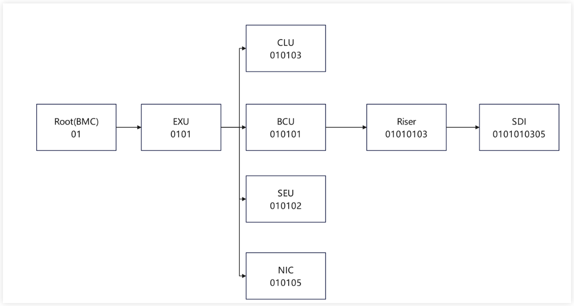
openUBMC discovers hardware components based on the toplogy of the server. In a typical Tianchi server design, BMC card is connected to the EXU(Extension Unit), which also connects the BCU(Basic Computing Unit), CLU(Cooling Unit), SEU(Storage Expansion Unit) and PSU(Power Supply Unit). IEU(IO Extension Unit) is connected to the BCU and PCIe Cards are connected to the IEU. openUBMC follows breath-first search algorithm to discover the hardware components level by level via Connector. For details about the hardware discovery process, please refer to Hardware Self-Discovery for more details.
Due to the discovery process, CSR are conncted by Connector. Therefore, Connector contains the association information between CSRs. For details, please refer to Connector Object.
Example of Component Discover Process
Check the Connector object in DBus
shell~~# busctl --user tree bmc.kepler.hwdiscovery └─/bmc └─/bmc/kepler ├─/bmc/kepler/Connector │ ├─/bmc/kepler/Connector/Connector_EXU_1_01Figure 1 shows that root.csr -> EXU. You can view the Connector information of root.csr to find the CSR file of the EXU board.
shell~~# busctl --user introspect bmc.kepler.hwdiscovery /bmc/kepler/Connector/Connector_EXU_1_01 NAME TYPE SIGNATURE RESULT/VALUE FLAGS bmc.kepler.Connector interface - - - .AuxId property s "01" emits-change writa> .Bom property s "14100513" emits-change .Buses property as 0 emits-change .ChassisId property s "" emits-change .GroupId property u 2 emits-change .GroupPosition property s "0101" emits-change .Id property s "EXU" emits-change writa> .IdentifyMode property y 2 emits-change .LoadStatus property y 0 emits-change .ManagerId property s "1" emits-change .Presence property y 1 emits-change writa> .SilkText property s "EXU" emits-change .Slot property y 1 emits-change writa> .SystemId property y 1 emits-change .Type property s "" emits-change bmc.kepler.Object.Properties interface - - - .GetAllWithContext method a{ss}s a{sv} - .GetOptions method a{ss}ss a{ss} - .GetPropertiesByNames method a{ss}sas a{sv}a{sv} - .GetPropertiesByOptions method a{ss}sa{ss} as - .GetWithContext method a{ss}ss v - .SetWithContext method a{ss}ssv - - .ClassName property s "Connector" emits-change .ObjectIdentifier property (ysss) 0 "1" "" "01" emits-change .ObjectName property s "Connector_EXU_1_01" emits-changeExplanation:
a. According to the preceding resource collaboration interface information, the Connector object that connects to the downstream board 14100513_EXU_01.csr in root.csr is Connector_EXU_1. For details, see bmc.kepler.Object.Properties.
b. The attributes and attribute values of Connector_EXU_1 are mounted to the bmc.kepler.Connector interface. You can query the value of IdentifyMode to determine whether to use the Tianchi or non-Tianchi component to load the downstream component.
c. IdentifyMode = 2 indicates the non-Tianchi loading mode. Combine the Bom, Id, and AuxId to search for the downstream component Bom_Id_AuxId.csr.
d. IdentifyMode = 3 indicates the Tianchi loading mode. Combine the Bom and Id to search for the downstream component Bom_Id.csr.
Connector Object
Connector is a logical concept. In CSR, different components are connected through connectors. Therefore, the correct configuration of the Connector object is crucial to load the downstream components.
Common Connector Configuration
{
    "Connector_xxx": {
        "Bom": ,
        "Slot": ,
        "Position": ,
        "Presence": ,
        "Id": ,
        "AuxId": ,
        "Buses": [],
        "SystemId": ,
        "SilkText": ,
        "IdentifyMode": ,
        "Type": ,
        "ManagerId": ,
        "ChassisId": ,
        "Chip": ,
        "Container": ,
        "IdChipAddr": ,
    }
}
Explanation:
- The CSR specification defines a Connector object's name as
ClassName.InstanceIdentifier, which must be globally unique across the CSR. - Configure the attributes of the Connector object following this table.
| Attribute | Value Type | Description | Mandatory or Optional |
|---|---|---|---|
| Bom | U8 | BOM ID of the downstream component. | Optional |
| Slot | U8 | Signal slot of the downstream component. | Mandatory |
| Position | U8 | Global position ID of a CSR object, which is required when the object is renamed during hardware self-discovery. Any two Connectors in the same CSR file must not have duplicate positions. | Mandatory |
| Presence | U8 | Method for obtaining the Presence status. It can be set as a static value of 0 or 1, dynamic reference, data synchronization, or an expression whose calculation result is 0 or 1. The Presence status obtaining method must be specified for Tianchi components. Generally, this is done by the hardware proxy to read the register data of the specified component using the attribute synchronization syntax. | Mandatory |
| Id | String | UID of the downstream component. To obtain the UID of a Tianchi component, the component object associated with the Chip attribute invokes the corresponding read/write interface to obtain the UID of the EEPROM data. | Optional |
| AuxId | String | Aux ID of the downstream component. This attribute is not used by Tianchi components. Non-Tianchi components use this attribute when loading downstream boards/cards. However, this attribute can be left empty. | Optional |
| Buses | String[] | Bus connected to the downstream component. The value is a character string array, which contains 0 to multiple buses. The name of each configured bus must be the same as the Buses name in Anchor or be defined under Pca9544, Pca9555, Pca9548, Chip, Smc, or JtagSwitch. | Mandatory |
| SystemId | U8 | Displayed only in Connector in root.sr, indicating the System to which the downstream CSR object belongs. For a single system, set the default value 1. For multiple systems, configure multiple connectors and set SystemId to different values, starting from 1 and increasing. | Optional |
| SilkText | String | Silkscreen information of the downstream component. | Optional |
| IdentifyMode | U8 | Identification mode of the downstream component. IdentifyMode = 1: indicates that BoardId is readable, and the BoardId loading mode is used to directly associate with an Accessor and directly read data from the hardware. IdentifyMode = 2: indicates the non-Tianchi component loading mode. IdentifyMode = 3: indicates the Tianchi component loading mode. | Mandatory |
| Type | String | Type of the back-end device of a connector, such as PCIeSlot, PCIeRiser, and SEU. | Optional |
| ManagerId | String | Defined only in Connector in root.sr, indicating the Manager to which the downstream CSR object belongs. This is a software attribute. | Optional |
| ChassisId | String | Defined only in Connector in root.sr, indicating the Chassis to which the downstream CSR object belongs. This is a software attribute. | Optional |
| Chip | String | Associated register object. | Optional |
| Container | String | Hardware position of the downstream component, indicating the actual physical position of the component. | Optional |
| IdChipAddr | U8 | This address is used to obtain the EEPROM ID. | Optional |
| CSRVersion | String | Real hardware self-description data version in Eeprom of hardware self-discovery settings. | Optional |
Loading Modes
IdentifyMode is used to define whether the downstream component is Tianchi or not. If set to 3, openUBMC will load the CSR from Eeprom following the Tianchi discovery process. If set to 2, then it will load from local CSR.
root.sr -> EXU -> BCU/SEU/CLU/PSR -> IEU (I/O expansion component) -> PCIe
Loading Mode of Tianchi Components
Take the BCU Connector on the EXU as an example (as shown in Figure 1). If the Presence attribute of Connector_BCU is 1, that is, the connected BCU is present. In this case, the framework automatically reads the register (EEPROM) of the downstream object, parses and verifies the UID (unique identifier of each Tianchi component) in the header data in the EEPROM, updates Connector ID, parses the binary data of the EEPROM, and distributes the downstream object. The framework obtains the Bom_Id.sr of the downstream object based on the Bom attribute of the Connector and the UID in the parsed EEPROM data, and directly loads the downstream object file in the EEPROM.
Loading Mode of Non-Tianchi Components
Take the PCIe Connector of the Riser card as an example (as shown in Figure 1). During initialization, the PCIe Device component sends an ipmi command to the BIOS to obtain the 4-tuple of the PCIe card in in-band mode and update Connector id and AuxId. Similarly, if the value of the Presence attribute is 1, the downstream component object of the connector is present. In this case, the framework checks whether the Bom_Id_AuxId.sr and Bom_Id_AuxId_soft.sr object files exist and directly loads the built-in .sr file of the BMC.
Component Configuration
It is recommended that developers use BMC Studio to configure CSR files as it offers comprehensive guidance to help developers quickly and accurately configure CSR files.
The following uses a riser card as an example to describe how to configure and adapt a component.
A riser card is an adapter card used to expand slots of a computer mainboard. It changes the slot direction on the mainboard from vertical to horizontal so that other internal components can be easily accommodated, especially in a small or space-constrained computer chassis. The riser card is usually used to add more expansion cards, such as audio cards, video cards, and network adapters.
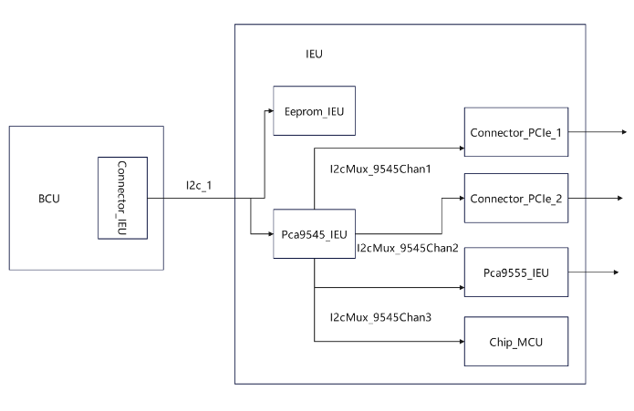
The following describes the management topology of the riser card based on its hardware diagram.
 json
json{ "FormatVersion": "3.00", "DataVersion": "1.00", "Unit": { "Type": "IEU", "Name": "RiserCard_1" }, "ManagementTopology": { "Anchor": { "Buses": [ "I2c_1" ] }, "I2c_1": { "Chips": [ "Eeprom_IEU", "Pca9545_IEU" ] }, "Pca9545_IEU": { "Buses": [ "I2cMux_9545Chan1", "I2cMux_9545Chan2", "I2cMux_9545Chan3" ] }, "I2cMux_9545Chan1": { "Connectors": [ "Connector_PCIe_1" ] }, "I2cMux_9545Chan2": { "Connectors": [ "Connector_PCIe_2" ] }, "I2cMux_9545Chan3": { "Chips": [ "PCA9555_IEU", "Chip_MCU" ] } } }Explanation: Configure the relationship between FormatVersion, DataVersion, Unit, and ManagementTopology of the riser card based on the riser card management topology shown in Figure 1.
Determine the objects required for configuring a riser card, the attributes of the objects, and the sources of the values.
- When configuring a riser card, you must configure the RiserCard object to describe the information about the riser card.
json{ "Objects": { "RiserCard_1": { "Slot": 1, "UID": "00000001040302023940", "Name": "BC83PRUI", "Manufacturer": "openUBMC", "Type": "IEU", "Description": "Riser(X8*2)", "PartNumber": "0302023940", "PcbID": "#/Accessor_PcbID.Value", "PcbVersion": "", "LogicVersion": "N/A", "SRVersion": "${DataVersion}", "MCUVersion": "", "BoardID": 65535, "BoardType": "RiserCard", "Number": 1, "DeviceName": "PCIeRiser${Slot}", "Position": "chassis", "NodeId": "chassisPCIeRiser${Slot}", "FruID": "<=/Fru_IEU.FruId", "RefMCUChip": "#/Chip_MCU" } } }Explanation:
a. The RiserCard_1 object describes the information about the riser card as follows: The riser card is located in slot 1 of the BCU. The UID that uniquely identifies the riser card is 00000001040302023940. The card name is BC83PRUI. Some riser card information is displayed on the WebUI.
b. For details about the configuration description of each attribute of the RiserCard object, see Object Configuration > RiserCard.
2.2 According to the object description of RiserCard_1, the RiserCard needs to reference the MCU register and the MCU is a logic chip that needs to be upgraded. Therefore, you need to configure the object that describes an MCU upgrade and MCU register information.
json{ "Objects": { "Chip_MCU": { "OffsetWidth": 1, "AddrWidth": 1, "Address": 200, "WriteTmout": 100, "ReadTmout": 100, "HealthStatus": 0, "WriteRetryTimes": 2, "ReadRetryTimes": 0, "DrvWriteDelay": "<=/RiserCard_1.MCUVersion |> string.sub($1, 1, 4) |> expr($1 >= '1.12' ? 0 : 1)" }, "MCUFirmware_1": { "UID": "00000001040302023940", "RefChip": "#/Chip_MCU", "Address": 200, "SoftwareId": "MCU-BC83PRUI", "BoardType": "IEU" } } }Explanation:
a. Describe the information about the register where the MCU is located and the MCU upgrade information.
b. For details about the configuration description of each attribute of the Chip_MCU object, see Object Configuration > Chip.
c. For details about the configuration description of each attribute of the MCUFirmware_1 object, see Object Configuration > MCU Upgrade.
2.3 The riser card is a Tianchi component and uses EEPROM to store CSR data that needs to be updated. Therefore, you need to configure the Eeprom object and SR upgrade object.
json{ "Objects": { "Eeprom_IEU": { "OffsetWidth": 2, "AddrWidth": 1, "Address": 174, "WriteTmout": 100, "ReadTmout": 100, "RwBlockSize": 32, "WriteInterval": 20, "HealthStatus": 0 }, "SRUpgrade_1": { "UID": "00000001040302023940", "Type": "IEU", "Version": "${DataVersion}", "StorageChip": "#/Eeprom_IEU", "SoftwareId": "HWSR-BC83PRUI", "WriteProtect": "#/Accessor_IEUWP.Value" } } }Explanation:
a. It describes the EEPROM information of the IEU component because EEPROM is used to store Fru and CSR information. Therefore, when the CSR information stored in the EEPROM needs to be upgraded, configure the SRUpgrade object. The object configures information such as the name (UID.sr) of the CSR file package to be upgraded, data version of the CSR file to be upgraded, and register of the EEPROM that stores CSR.
b. For details about the configuration description of each attribute of the Eeprom_IEU object, see Object Configuration > Eeprom.
c. For details about the configuration description of each attribute of the SRUpgrade_1 object, see Object Configuration > SR Upgrade.
2.4 A riser card is an adapter card used to expand slots of a computer mainboard. It has many slots, where PCIe cards or other multiplexers can be inserted. The Pca9545 multiplexer is used on the riser card to connect more devices.
json{ "Objects": { "Pca9545_IEU": { "OffsetWidth": 0, "AddrWidth": 1, "Address": 226, "WriteTmout": 100, "ReadTmout": 100, "HealthStatus": 0 }, "I2cMux_9545Chan1": { "ChannelId": 1 }, "I2cMux_9545Chan2": { "ChannelId": 2 }, "I2cMux_9545Chan3": { "ChannelId": 3 } } }Explanation:
a. Here, the information about the Pca9545 multiplexer connected to the riser card is described. The three channels of the Pca9545 multiplexer are used to expand the line.
b. For details about the configuration description of each attribute of the Pca9545_IEU object, see Object Configuration > Pca9545.
2.5 Since the Pca9545 multiplexer is used to expand the number of devices, the following describes the information about the devices mounted to the three channels of Pca9545.
json{ "Objects": { "Connector_PCIe_1": { "Bom": "14140130", "Slot": 1, "Position": 1, "Presence": 0, "Id": "", "AuxId": "", "Buses": [ "I2cMux_9545Chan1" ], "SystemId": "${SystemId}", "ManagerId": "${ManagerId}", "ChassisId": "${ChassisId}", "SilkText": "RiserCard${Slot}", "IdentifyMode": 2, "Container": "Component_RiserCard", "Type": "PCIe" } } }Explanation:
a. A PCIe device is mounted to the I2cMux_9545Chan1 channel of Pca9545. Herein, how to search for the information about the connected downstream PCIe device is described.
b. For details about the configuration description of each attribute of the Connector_PCIe_1 object, see Connector.
json{ "Objects": { "Connector_PCIe_2": { "Bom": "14140130", "Slot": 2, "Position": 2, "Presence": 0, "Id": "", "AuxId": "", "Buses": [ "I2cMux_9545Chan2" ], "SystemId": "${SystemId}", "ManagerId": "${ManagerId}", "ChassisId": "${ChassisId}", "SilkText": "RiserCard${Slot}", "IdentifyMode": 2, "Container": "Component_RiserCard", "Type": "PCIe" } } }Explanation:
a. Another PCIe device is mounted to the I2cMux_9545Chan2 channel of Pca9545. Herein, how to search for the information about the connected downstream PCIe device is described.
b. For details about the configuration description of each attribute of the Connector_PCIe_2 object, see Connector.
json{ "Objects": { "Pca9555_IEU": { "OffsetWidth": 1, "AddrWidth": 1, "Address": 64, "WriteTmout": 100, "ReadTmout": 100, "HealthStatus": 0 }, "Scanner_Riser3V3Event": { "Chip": "#/Pca9555_IEU", "Offset": 1, "Size": 1, "Mask": 16, "Type": 0, "Period": 400, "Debounce": "#/Cont_num5", "Value": 0 }, "Accessor_PcbID": { "Chip": "#/Pca9555_IEU", "Offset": 1, "Size": 1, "Mask": 192, "Type": 0, "Value": 0 }, "Accessor_IEUWP": { "Chip": "#/Pca9555_IEU", "Size": 1, "Offset": 1, "Mask": 8, "Type": 0, "Value": 0 }, "Event_Riser3V3Event": { "EventKeyId": "Riser.PowerFailure", "Condition": 0, "Reading": "<=/Scanner_Riser3V3Event.Value", "@Default": { "Reading": 1 }, "OperatorId": 5, "Enabled": false, "AdditionalInfo": "1", "DescArg1": "#/RiserCard_1.Slot", "Component": "#/Component_RiserCard" }, "Cont_num5": { "Num": 5, "DefaultValue": 1 } } }Explanation:
a. The I2cMux_9545Chan3 channel of the Pca9545 is mounted with the register where the MCU is located (for details, see the preceding description) and the Pca9555 multiplexer.
b. The PcbID needs to be associated with the hardware. Therefore, the Accessor object needs to be configured to read the hardware where the PcbID is located.
c. The riser card has the 3.3 V voltage. You need to periodically scan the 3.3 V voltage information and configure related alarm events. For details about how to configure the event, see Event Customization. For details about how to configure the scanner, see Object Configuration > Scanner.
d. When data is read from the register, false alarms may occur due to component jitter. In this case, configure a filter to filter out abnormal scenarios. For details about the Cont configuration, see Object Configuration > Cont.
e. The Accessor_IEUWP object is used to set the write protection switch of the EEPROM. Possible values are 0: off; 1: on.
2.6 A riser card is a field replaceable unit (FRU). You need to configure the Fru type object to describe it.
json{ "Objects": { "Fru_IEU": { "PcbId": 1, "FruId": 1, "FruName": "PCIe Riser${Slot}", "ConnectorGroupId": "${GroupId}", "BoardId": 65535, "UniqueId": "00000001040302023940", "PcbVersion": ".A", "PowerState": 1, "Health": 0, "EepStatus": "<=/Eeprom_IEU.HealthStatus", "Type": 195, "FruDataId": "#/FruData_IEU" }, "FruData_IEU": { "FruId": 1, "FruDev": "#/Eeprom_IEU", "EepromWp": "#/Accessor_IEUWP.Value", "StorageType": "TianChi" }, "Component_RiserCard": { "FruId": "<=/Fru_IEU.FruId", "Instance": 0, "Type": 15, "Location": "<=/RiserCard_1.Position", "Name": "<=/RiserCard_1.DeviceName", "Presence": 1, "Health": 0, "PowerState": 1, "GroupId": 1, "UniqueId": "<=/RiserCard_1.UID", "NodeId": "<=/RiserCard_1.Position;<=/RiserCard_1.DeviceName |> string.format('%s%s',$1,$2)", "BoardId": "<=/RiserCard_1.BoardID", "PartNumber": "<=/RiserCard_1.PartNumber" } } }Explanation:
a. A riser card is an FRU, and you need to use the Fru object to describe its overall information, electronic label information, and component information.
b. For the configuration description of each attribute of the Fru_IEU class, see Object Configuration > Fru Class > Fru.
c. For the configuration description of each attribute of the FruData_IEU class, see Object Configuration > Fru Class > FruData.
d. For the configuration description of each attribute of the Component_RiserCard object, see Object Configuration > Fru Class > Component.
2.7 The riser card is mounted to the I2C link, and the Pca9545 and Pca9555 multiplexers are mounted to the riser card. Perform self-check for these links to provide query interfaces for the equipment test phase.
json{ "Objects": { "DftPca9555_1": { "Type": 1, "Id": 3, "Slot": "${GroupId}", "DeviceNum": 0, "ItemName": "PCA9555 For IEU${Slot}", "PrompteReady": "", "PrompteFinish": "", "ProcessPeriod": 65535, "RefChip": "#/Pca9555_IEU" }, "DftPca9545_1": { "Type": 1, "Id": 4, "Slot": "${GroupId}", "DeviceNum": 0, "ItemName": "PCA9545 For IEU${Slot}", "PrompteReady": "", "PrompteFinish": "", "ProcessPeriod": 65535, "RefChip": "#/Pca9545_IEU" }, "DftI2c_1": { "Type": 1, "Id": 33, "DeviceNum": 0, "Slot": "${GroupId}", "ItemName": "I2C-${Slot} Test", "PrompteReady": "", "PrompteFinish": "", "ProcessPeriod": 65535, "RefChip": "#/Pca9545_IEU" } } }Explanation:
a. The DftPca9545_1 object is used to support the self-check of the Pca9545 component.
b. The DftPca9555_1 object is used to support the self-check of the Pca9555 component.
c. The DftI2c_1 object is used to support self-check over the I2C link. It achieves coverage by associating it with any simple component class for self-test, and in this case, the associated component is Pca9545.
json{ "Objects": { "DftEeprom_1": { "Id": 12, "Type": 1, "Slot": "${GroupId}", "DeviceNum": 0, "ItemName": "IEU Eeprom Self Test", "PrompteReady": "", "PrompteFinish": "", "ProcessPeriod": 65535, "FruData": "#/FruData_IEU" }, "DftEepromWp_1": { "Id": 47, "Type": 1, "Slot": "${GroupId}", "DeviceNum": 0, "ItemName": "IEU Eeprom Write Protect Self Test", "PrompteReady": "", "PrompteFinish": "", "ProcessPeriod": 65535, "FruData": "#/FruData_IEU" }, "DftVersion_RiserCardPcbVersion": { "FruId": "<=/Fru_IEU.FruId", "VersionType": 0, "Version": "<=/RiserCard_1.PcbVersion" }, "DftVersion_RiserCardCsrVersion": { "FruId": "<=/Fru_IEU.FruId", "VersionType": 25, "Version": "<=/RiserCard_1.SRVersion" }, "DftVersion_RiserCardMcuVersion": { "FruId": "<=/Fru_IEU.FruId", "VersionType": 27, "Version": "<=/RiserCard_1.MCUVersion" } } }Explanation: DftEeprom and DftEepromWp are used to support the write protection test of the EEPROM. DftVersion is used to support the version test.
2.8 Generally, a PCIe card is inserted into a riser card (the PCIe card can be found based on the Connector object configured above). If the configured PCIe card is not a Tianchi component, you need to obtain the 4-tuple information of the PCIe card in in-band mode to combine Id and AuxId, and then fill it into the Connector object. The downstream object is loaded during the hardware self-discovery.
Before obtaining the 4-tuple information in in-band mode, establish the mapping between the BCU port and IEU port. On the IEU side, the connection to the BCU side is implemented through the definition of BusinessConnector. The ports on both sides are in one-to-one mapping. Therefore, you need to find the upstream BCU objects for configuring the IEU. For details, see PCIe Configuration.
PSR.sr
json{ "Objects": { "UnitConfiguration_IEU2": { "SlotType": "IEU", "SlotNumber": 2, "SlotSilkText": "IEUSlot2", "Configurations": [ { "UID": "00000001040302023940", "Index": 2, "SrcPortName": [ "B2a", "B2c" ], "TargetPortID": [ 49, 50 ], "Slot": [ 5, 6 ], "Device": [] } ], "Port1LinkInfo": "" } } }BCU.sr
json{ "Objects": { "BusinessConnector_CPU2UBCDD1": { "Direction": "Downstream", "BCUIndex": "${Slot}", "Slot": 6, "LinkWidth": "X16", "MaxLinkRate": "PCIe 4.0", "ConnectorType": "UBCDD", "SilkText": "CPU2 UBCDD1", "UpstreamResources": [ { "Name": "SerDes_1_5", "ID": 5, "Offset": 0, "Width": 8 }, { "Name": "SerDes_1_6", "ID": 6, "Offset": 0, "Width": 8 } ], "ActualResourceOrder": [ "SerDes_1_6", "SerDes_1_5" ], "Ports": [ { "Name": "B2a", "ID": 5, "Offset": 0, "Width": 8 }, { "Name": "B2c", "ID": 7, "Offset": 8, "Width": 8 } ], "Port1LinkInfo": "", "Port2LinkInfo": "" }, "SerDes_1_5": { "Name": "SerDes_1_5", "ID": 5, "SocketID": 1, "LinkWidth": 8, "WorkMode": 1, "ModeConfigs": [ { "Mode": 1, "Device": [0,0,1,1,2,2,3,3], "ControllerIndex": [0,0,0,0,0,0,0,0] }, { "Mode": 4, "Device": [4,4,4,4,4,4,4,4], "ControllerIndex": [1,1,1,1,1,1,1,1] } ] }, "SerDes_1_6": { "Name": "SerDes_1_6", "ID": 6, "SocketID": 1, "LinkWidth": 8, "WorkMode": 1, "ModeConfigs": [ { "Mode": 1, "Device": [4,4,5,5,6,6,7,7], "ControllerIndex": [0,0,0,0,0,0,0,0] }, { "Mode": 1, "Device": [2,2,2,2,2,2,2,2], "ControllerIndex": [0,0,0,0,0,0,0,0] } ] }, } }RiserCard.sr
json{ "Objects": { "BusinessConnector_1": { "Name": "Up_1", "Direction": "Upstream", "Slot": 1, "LinkWidth": "X16", "MaxLinkRate": "PCIe 4.0", "ConnectorType": "UBCDD", "Ports": [ { "Name": "Down_1", "ID": 49, "Offset": 0, "Width": 8 }, { "Name": "Down_2", "ID": 50, "Offset": 8, "Width": 8 } ] }, "BusinessConnector_2": { "Name": "Down_1", "Direction": "Downstream", "Slot": 1, "LinkWidth": "X8", "MaxLinkRate": "PCIe 4.0", "ConnectorType": "PCIe CEM", "UpstreamResources": [ { "Name": "Up_1", "ID": 255, "Offset": 0, "Width": 8 } ], "RefMgmtConnector": "#/Connector_PCIe_1", "RefPCIeAddrInfo": "#/PcieAddrInfo_1" }, "BusinessConnector_3": { "Name": "Down_2", "Direction": "Downstream", "Slot": 2, "LinkWidth": "X8", "MaxLinkRate": "PCIe 4.0", "ConnectorType": "PCIe CEM", "UpstreamResources": [ { "Name": "Up_1", "ID": 255, "Offset": 8, "Width": 8 } ], "RefMgmtConnector": "#/Connector_PCIe_2", "RefPCIeAddrInfo": "#/PcieAddrInfo_2" } } }Explanation:
a. The BusinessConnector object of IEU.sr needs to be classified into two types: One is connected to the upstream BCU.sr, and the other is connected to the downstream PCIe device.
b. The connection to the upstream BCU is established through the UBCDD. Set ConnectorType of the BusinessConnector object to UBCDD. To configure some attributes of this object, find the corresponding PSR.sr and BCU.sr. Specifically, the IDs (49 and 50) of the Ports attribute of the BusinessConnector_1 object in the IEU.sr file must be the same as the TargetPortID value in the Configurations attribute of the UnitConfiguration_IEU2 object in the PSR.sr file. The SrcPortName attribute (B2a and B2c) and Slot attribute (5 and 6) of the Configurations object are the same as the Name and ID in the Ports attribute of the BusinessConnector_CPU2UBCDD1 object in the BCU.sr file. In addition, configure the SerDes_1_5 and SerDes_1_6 objects in the BCU.sr file. The Device attribute value of the SerDes object must be the same as the PortId value of the PCIeAddrInfo object, as the SocketID attribute indicates the model of the CPU connected to the SerDes. In this way, a mapping relationship between the BCU and IEU is established, and the RootBDF can be calculated based on the mapping relationship.
c. The connection to the downstream PCIe is established through the PCIe CEM. Set ConnectorType of the BusinessConnector object to PCIe CEM.
d. For details about the configuration description of the BusinessConnector_1, BusinessConnector_2, and BusinessConnector_3 objects, see Object Configuration > BusinessConnector.
2.9 Use the BusinessConnector object to establish the mappings between BCU and IEU and between IEU and PCIe and calculate the RootBDF based on the mapping between BCU and IEU. Then configure the PCIeAddrInfo object based on RootBDF and send the ipmi command in-band based on the attribute value to obtain the PCIe deviceBDF information.
json{ "Objects": { "PcieAddrInfo_1": { "Location": "RiserCard${Slot}", "ComponentType": 8, "ContainerSlot": "${Slot}", "ContainerUID": "00000001040302023940", "ContainerUnitType": "IEU", "GroupPosition": "PcieAddrInfo_1_${GroupPosition}" }, "PcieAddrInfo_2": { "Location": "RiserCard${Slot}", "ComponentType": 8, "ContainerSlot": "${Slot}", "ContainerUID": "00000001040302023940", "ContainerUnitType": "IEU", "GroupPosition": "PcieAddrInfo_2_${GroupPosition}" } } }Explanation:
a. The PcieAddrInfo_1 object is configured to send SlotId, SocketId, and DeviceId in-band to obtain the PCIe deviceBDF information that is then used to query the 4-tuple information about PCIeDevice. Based on the 4-tuple, combine Id and AuxId and fill it into Connector_PCIe_1 to load the downstream PCIe device during hardware self-discovery. For details, see PCIe Configuration.
b. The PcieAddrInfo_2 object is configured to send SlotId, SocketId, and DeviceId in-band to obtain the PCIe deviceBDF information that is then used to query the 4-tuple information about PCIeDevice. Based on the 4-tuple, combine Id and AuxId and fill it into Connector_PCIe_2 to load the downstream PCIe device during hardware self-discovery. For details, see PCIe Configuration.
The CSR file of a riser card has been configured. The next step is to perform component adaptation and check whether the riser card can be successfully loaded in the environment.
Component Adaptation
Loading a Component
Use the BMC built-in mode.
a. Configure the Bom_id.sr file of the riser card in the VPD component repository, for example, riser_00000001040302023940.sr.
b. Configure or modify the information about the Connector object connected to the riser card in the CSR file of the BCU.
json{ "Objects": { "Connector_IEU_1": { "Bom": "14100513", "Slot": 1, "Position": 1, "Presence": 1, "Id": "", "AuxId": "", "Buses": [], "SystemId": 1, "SilkText": "IEU", "IdentifyMode": 2, "Container": "Component_RiserCard" } } }c. Add the riser card file path to the profile file.
shell/sr/riser_00000001040302023940.srd. Generate the package and verify it in the environment. For details about the package generation process, see BMC Studio CLI (bingo) and BMC Studio User Guide.
Use the EEPROM format.
a. Pack the configured uid.sr file of the riser card, for example, riser_00000001040302023940.sr, into an IMG package. For details, see BMC Studio User Guide.
b. Upgrade the IMG package of the riser card in the environment.
c. Verify it in the environment.
Environment Verification
Find the file in the environment.
shell~ ~ $ find / -name riser_00000001040302023940.sr ../sr/riser_00000001040302023940.srRun the busctl command in the environment to view information about RiserCard to which the resource collaboration interface is mounted.
shell~ ~ $ busctl --user introspect bmc.kepler.general_hardware /bmc/kepler/Systems/1/Boards/RiserCard/RiserCard_1_01010101 NAME TYPE SIGNATURE RESULT/VALUE FLAGS bmc.kepler.Object.Properties interface - - - .GetAllWithContext method a{ss}s a{sv} - .GetOptions method a{ss}ss a{ss} - .GetPropertiesByNames method a{ss}sas a{sv}a{sv} - .GetPropertiesByOptions method a{ss}sa{ss} as - .GetWithContext method a{ss}ss v - .SetWithContext method a{ss}ssv - - .ClassName property s "RiserCard" emits-change .ObjectIdentifier property (ysss) 1 "1" "" "01010101" emits-change .ObjectName property s "RiserCard_1_01010101" emits-change bmc.kepler.Systems.Board interface - - - .BoardID property q 65535 emits-change .BoardType property s "RiserCard" emits-change .CpldStatus property y 255 emits-change .Description property s "Riser(X8*2)" emits-change .DeviceName property s "PCIeRiser1" emits-change .FruID property y 0 emits-change .LogicUnit property u 0 emits-change .LogicVersion property s "N/A" emits-change .MCUVersion property s "" emits-change .Manufacturer property s "openUBMC" emits-change .MultiLogicUnit property a{su} 0 emits-change .MultiLogicVersion property a{ss} 0 emits-change .Name property s "BC83PRUI" emits-change .NodeId property s "chassisPCIeRiser1" emits-change .Number property y 1 emits-change .PSIPVersion property s "" emits-change .PartNumber property s "0302023940" emits-change .PcbVersion property s ".A" emits-change .Position property s "chassis" emits-change .PowerWatts property u 0 - .ProductName property s "" emits-change .RefComponent property s "" emits-change .RefFru property s "" emits-change .RunningStatus property y 1 emits-change .SRVersion property s "1.00" emits-change .SerialNumber property s "" emits-change .SilkText property s "" emits-change .Slot property y 1 emits-change bmc.kepler.Systems.Board.Unit interface - - - .CurrentUpgradeStatus property y 0 emits-change .HWSRVersion property s "" emits-change .Type property s "IEU" emits-change .UID property s "00000001040302023940" emits-change
Object Configuration
RiserCard
During the component loading and adaptation, the RiserCard object is used to describe the riser card information.
Common attribute structure of RiserCard
{
    "RiserCard_xxx": {
        "Slot": ,
        "Number": ,
        "Position": ,
        "Name": ,
        "ProductName": ,
        "SilkText": ,
        "Manufacturer": ,
        "Description": ,
        "BoardID": ,
        "PartNumber": ,
        "PcbVersion": ,
        "LogicVersion": ,
        "SRVersion": ,
        "MCUVersion": ,
        "LogicUnit": ,
        "PowerWatts": ,
        "RunningStatus": ,
        "FruID": ,
        "DeviceName": ,
        "BoardType": ,
        "NodeId": ,
        "RefComponent": ,
        "RefFru": ,
        "SerialNumber": ,
        "CpldStatus": ,
        "UID": ,
        "Type": ,
        "PcbID": ,
        "LogicVersionID": ,
        "RefMCUChip": ,
        "RefSMCChip": ,
        "Container": ,
        "CpldTestNum":
    }
}
Explanation:
- The CSR specification defines a RiserCard object's name as
ClassName.InstanceIdentifier, which must be globally unique across the CSR. - Configure the attributes of the RiserCard object following this table.
| Attribute | Value Type | Description |
|---|---|---|
| Slot | U8 | Physical slot number of the BCU where RiserCard is located. For example, Slot = 1 indicates that RiserCard is located in slot 1 of the BCU. |
| Number | U8 | Logical number of RiserCard. |
| Position | String | Container information about RiserCard, for example, chassis. |
| Name | String | Component name, for example, BC83PRUI. |
| ProductName | String | Product name. |
| SilkText | String | Silkscreen information about RiserCard. |
| BoardID | U16 | Board ID, which is mainly used in non-Tianchi components. |
| PartNumber | String | Part number, which is displayed on the WebUI. |
| PcbVersion | String | PCB version, which is calculated based on the value of PcbId. When PcbId is 1, .A is displayed; when it is 2, .B is displayed; and so on. |
| LogicVersion | String | Logical version of the Cpld on RiserCard. |
| SRVersion | String | Version of the CSR data in the EEPROM on RiserCard. Generally, the value is the same as that of DataVersion in the CSR file. |
| MCUVersion | String | MCU version on RiserCard. |
| LogicUnit | U32 | Logic unit on RiserCard. |
| PowerWatts | U32 | Power of RiserCard. |
| RunningStatus | U8 | Running status of the CPLD and MCU. Value 1 indicates normal while value 0 indicates abnormal. |
| FruID | U8 | FruID attribute of the associated Fru object. This attribute must be configured for each pluggable object. |
| DeviceName | String | Silkscreen information about a component, for example, PCIe Riser1. |
| BoardType | String | Board type, which is of the enumerated type. For example, RiserCard. |
| NodeId | String | Resource ID, which is composed of the container information Position and device silkscreen name DeviceName. For example, if the container information Position is chassis and DeviceName is PCIeRiser1, NodeId is chassisPCIeRiser1. |
| RefComponent | String | Describes the referenced Component object. |
| RefFru | String | Referenced Fru object. |
| SerialNumber | String | Serial number, which is related to the electronic label and is obtained through RefFru. It uniquely identifies a card and can be used to query the manufacturing process of the card. |
| CpldStatus | U8 | Health status of Cpld. |
| UID | String | Unique ID of a component, which is used to find the CSR file of the component. |
| Type | String | Component type (enumerated values: EXU, BCU, SEU, CLU, and IEU). |
| PcbID | U8 | PCB version ID, which needs to be associated with the hardware and read from the hardware. |
| LogicVersionID | U8 | Version ID of Cpld. |
| RefMCUChip | U8B[] | Register of the referenced MCU. |
| RefSMCChip | U8[] | Register of the referenced SMC. |
| Container | String | Container information. |
| CpldTestNum | U8 | Cpld test sequence number. |
| Manufacturer | String | Manufacturer of the riser card. |
| Description | String | Slot information about the riser card. For example, Riser (X8*2) indicates that the riser card has two slots whose physical width and signal bandwidth are both x8. This means that the riser card supports two x8 expansion cards, or one x16 expansion card (if supported because the x16 slot is compatible with the x8 card). |
MCU Upgrade
An MCU is a microcontroller unit that needs to be upgraded in the CSR file.
Common attribute structure of an MCU object to be upgraded
{
    "MCUFirmware_xxx": {
        "UID": ,
        "RefChip": ,
        "Address": ,
        "Protocol": ,
        "SoftwareId": ,
        "BoardType": ,
        "LockChip":
    }
}
Explanation:
- The CSR specification defines a MCUFirmware object's name as
ClassName.InstanceIdentifier, which must be globally unique across the CSR. - Configure the attributes of the MCUFirmware object following this table.
| Attribute | Value Type | Description |
|---|---|---|
| UID | String | Unique ID of a component, used to search for the upgrade package of the corresponding MCU firmware. |
| RefChip | U8[] | Register where the MCU is located. |
| Address | U32 | Address of the MCU in the register. |
| Protocol | String | Protocol used for communication with the MCU to transmit data, for example, SMC. |
| BoardType | String | Type of the component where the MCU is located, for example, IEU. |
| LockChip | U8[] | During an upgrade, the register needs to be locked. |
| SoftwareId | String | MCU software ID, for example, MCU-BC83PRUI. |
Chip
Chip is used to describe physical registers.
Common attribute structure of Chip
{
    "Chip_xxx": {
        "HealthStatus": ,
        "PowerStatus": ,
        "SelfTestResult": ,
        "Supported": ,
        "BaseOffset": ,
        "Length": ,
        "Period": ,
        "Address": ,
        "AddrWidth": ,
        "OffsetWidth": ,
        "WriteTmout": ,
        "ReadTmout": ,
        "WriteRetryTimes": ,
        "ReadRetryTimes": ,
        "DrvWriteDelay": ,
    }
}
Explanation:
- The CSR specification defines a Chip object's name as
ClassName.InstanceIdentifier, which must be globally unique across the CSR. - Configure the attributes of the Chip object following this table.
| Attribute | Value Type | Description |
|---|---|---|
| HealthStatus | U8 | Health status of the register where xxx is located. |
| PowerStatus | U8 | Power-on status of the register where xxx is located. |
| SelfTestResult | U8 | Self-check result of the register where xxx is located. |
| Address | U32 | Address of the register (where xxx is located) on the bus. |
| AddrWidth | U8 | Bit width. |
| OffsetWidth | U8 | Offset width. |
| WriteTmout | U32 | Timeout interval for writing to the register. |
| ReadTmout | U32 | Timeout interval for reading the register. |
| Supported | Boolean | Indicates whether the Chip has the data access aggregation capability. true: yes; false: no (default value). |
| BaseOffset | U32 | Start offset of aggregation resources or aggregation command word. In the SMC scenario, the attribute is the aggregation command word; in other block device scenarios, it is the start offset for continuously reading a segment of data. |
| Length | U32 | Total length of aggregation resources. |
| Period | U32 | Aggregation resource scan interval (unit: ms). |
| WriteRetryTimes | U8 | Number of retries for writing to the register. |
| ReadRetryTimes | U8 | Number of retries for reading the register. |
| DrvWriteDelay | U8 | - |
SR Upgrade
When the CSR file stored in the EEPROM needs to be updated, the SR upgrade object needs to be configured in the CSR file to notify the register where the EEPROM is located.
Common attribute structure of an SR object to be upgraded
{
    "SRUpgrade_xxx": {
        "UID": ,
        "Type": ,
        "Version": ,
        "StorageChip": ,
        "SoftwareId": ,
        "WriteProtect": ,
        "StorageLockChip": ,
        "WriteProtectChip": ,
        "WriteProtectLockChip":
    }
}
Explanation:
- The CSR specification defines a SRUpgrade object's name as
ClassName.InstanceIdentifier, which must be globally unique across the CSR. - Configure the attributes of the SRUpgrade object following this table.
| Attribute | Value Type | Description |
|---|---|---|
| UID | String | Unique ID of a component, which is used to search for the CSR file for upgrade. The CSR file is named UID.CSR. |
| Type | String | Type of the component where the SR upgrade object is located. |
| Version | String | Data version of the SR to be upgraded. |
| StorageChip | U8[] | Chip that stores CSR files. |
| WriteProtect | String | Write protection information about the EEPROM. Before upgrading the CSR of the EEPROM, disable the write protection to allow data writes or modification. |
| StorageLockChip | U8[] | Locks the EEPROM register that stores CSR files during the CSR file upgrade of the EEPROM. |
| WriteProtectChip | U8[] | Write protection register. |
| WriteProtectLockChip | U8[] | Register with the write protection lock. |
Eeprom
According to the Tianchi architecture specifications, each component must have a storage device with the I2C bus address 0xAE. Currently, it is the Eeprom device, which is used to store hardware self-description information, including the header, electronic label, component self-description record (CSR), and extended information.
Common attribute structure of Eeprom
{
    "Eeprom_xxx": {
        "HealthStatus": ,
        "PowerStatus": ,
        "SelfTestResult": ,
        "Address": ,
        "AddrWidth": ,
        "OffsetWidth": ,
        "WriteTmout": ,
        "ReadTmout": ,
        "RwBlockSize": ,
        "WriteInterval":
    }
}
Explanation:
- The CSR specification defines a Eeprom object's name as
ClassName.InstanceIdentifier, which must be globally unique across the CSR. - Configure the attributes of the Eeprom object following this table.
Address must be the same as the hardware design
| Attribute | Value Type | Description |
|---|---|---|
| HealthStatus | U8 | Health status of Eeprom. |
| PowerStatus | U8 | Power-on status of Eeprom. |
| SelfTestResult | U8 | Self-check result of Eeprom. |
| Address | U32 | Address of Eeprom on the bus. |
| AddrWidth | U8 | Address bit width of Eeprom. |
| OffsetWidth | U8 | Offset bit width of Eeprom. |
| WriteTmout | U32 | Write timeout interval of Eeprom |
| ReadTmout | U32 | Read timeout interval of Eeprom |
| RwBlockSize | U16 | Size of the data written to Eeprom by segment. |
| WriteInterval | U16 | Delay of writing Eeprom by segment. |
Pca9545
Pca9545 is an I2c multiplexer used to extend bus channels. It can split a bus into four independent channels, each of which can connect to different secondary devices. You can enable one of the channels by writing a specific bit in the internal registers of Pca9545. Only one channel can be enabled at a time. Pca9545 is often used in hardware design to increase the number of secondary devices, especially when multiple devices are required but the number of buses is limited.
Common attribute structure of Pca9545
{
    "Pca9545_xxx": {
        "HealthStatus": ,
        "PowerStatus": ,
        "SelfTestResult": ,
        "Address": ,
        "AddrWidth": ,
        "OffsetWidth": ,
        "WriteTmout": ,
        "ReadTmout": ,
    }
}
Explanation:
- The CSR specification defines a Pca9545 object's name as
ClassName.InstanceIdentifier, which must be globally unique across the CSR. - Configure the attributes of the Pca9545 object following this table.
Addressmust be the same as the hardware design in order to allow openUBMC to switch the channel correctly.- Pca9545 is also a register and it has only one channel that can operate. Switching between channels may involve read/write timeout issues, so relevant attributes need to be configured.
| Attribute | Value Type | Description |
|---|---|---|
| HealthStatus | U8 | Health status of Pca9545. |
| PowerStatus | U8 | Power-on status of Pca9545. |
| SelfTestResult | U8 | Self-check result of Pca9545. |
| Address | U32 | Address of Pca9545 on the bus. |
| AddrWidth | U8 | Address bit width of Pca9545. |
| OffsetWidth | U8 | Offset bit width of Pca9545. |
| WriteTmout | U32 | Timeout interval for writing to the Pca9545. |
| ReadTmout | U32 | Timeout interval for reading the Pca9545. |
Scanner
When a Scanner object is configured in the CSR file, the object periodically scans its referenced registers and updates the obtained attribute values to the resource collaboration interface. This is only used in read-only scenarios.
Common attribute structure of Scanner
{
    "Scanner_xxx": {
        "Chip": ,
        "Offset": ,
        "Size": ,
        "Mask": ,
        "Type": ,
        "Period": ,
        "Debounce": ,
        "Value": ,
        "AggregateOffset": ,
        "ScanEnabled": ,
        "NominalValue": ,
        "FailureDebounceCount": ,
        "SuccessDebounceCount":
    }
}
Explanation:
- The CSR specification defines a Scanner object's name as
ClassName.InstanceIdentifier, which must be globally unique across the CSR. - Configure the attributes of the Scanner object following this table.
NOTE
a. Since Scanner is signal provider, when referencing in CSR, <=/ shall be used instead of #/ in order to receive the property changed signal correctly.
b. Scanner must be used by at least one other object.
c. You only need to set the Chip attribute for the Scanner associated with the Chip.
Key parameters:
| Attribute | Value Type | Description |
|---|---|---|
| Chip | String | Chip referenced by the Scanner, that is, the Chip is periodically scanned and read. This field is mandatory, and the Chip object referenced by the Scanner must be defined in the Objects. The Chip objects that can be referenced do not include Pca9544, Pca9545, Pca9548, and JtagSwitch. |
| Offset | U32 | Offset of the read data. The offset needs to be calculated based on the SMC command. JSON does not support hexadecimal and needs to be converted into decimal. |
| Size | U8 | Size of the read data. This field is mandatory. |
| Mask | U32 | Mask of the read data. This field is valid only for bit read and can be set to 0 (meaning invalid) for block read. This field is mandatory when Type is set to 0. |
| Type | U8 | 0: bit read; 1: block read. This field is mandatory. The value can only be 0 or 1. |
| Period | U32 | Scanning period (unit: ms). |
| Debounce | String | Anti-jitter type. This field is optional. The referenced anti-jitter object must be defined in Objects. The anti-jitter object types include MidAvg, Median, Cont, and ContBin. This field can also be set to the constant character string None. |
| Value | U64 | Value read by the Scanner. The default value is 0. |
| AggregateOffset | U32 | Relative offset of the Scanner in the aggregated data. The value ranges from 0 to 1023. Generally, this field is optional; but if the offset field is not set, AggregateOffset is mandatory. |
| ScanEnabled | U8 | Indicates whether periodic scanning is supported. |
| NominalValue | U64 | Normal value. |
| FailureDebounceCount | U8 | Number of anti-jitter failures. |
| SuccessDebounceCount | U8 | Number of anti-jitter successes. |
Accessor
Accessor is applicable to scenarios where values do not need to be obtained cyclically and periodically or hardware values need to be written. The attribute is readable and writable. When a value is obtained, the framework listens to read-only signals, reads the hardware values in real time, and updates them to the resource collaboration interface. When a value is written, the framework listens to change signals and writes them to the hardware in real time.
Accessor configuration example
{
    "Accessor_xxx": {
        "Chip": ,
        "Offset": ,
        "Size": ,
        "Mask": ,
        "Type": ,
        "Value": ,
        "FailureDebounceCount": ,
        "SuccessDebounceCount":
    }
}
Explanation:
- The CSR specification defines a Accessor object's name as
ClassName.InstanceIdentifier, which must be globally unique across the CSR. - Configure the attributes of the Accessor object following this table.
NOTE
Every Accessor defined in the CSR must be referenced by other objects to avoid wasting hardware access resources.
| Attribute | Value Type | Description |
|---|---|---|
| Chip | string | Chip referenced by the Accessor. That is, read and write operations are performed on the Chip. This field is mandatory. |
| Offset | U32 | Offset of the data. The offset must be the same as that of the SMC command word. JSON does not support hexadecimal and needs to be converted into decimal. This field is optional. |
| Size | U8 | Size of the data read and written by the Accessor. This field is mandatory. |
| Mask | U32 | Mask. This field is valid only for bit read and can be set to 0 (meaning invalid) for block read. This field is mandatory. |
| Type | U8 | 0: bit read; 1: block read. This field is mandatory. |
| Value | U64 | Value read by the Accessor. The default value is 0. |
| FailureDebounceCount | U8 | Number of anti-jitter failures. |
| SuccessDebounceCount | U8 | Number of anti-jitter successes. |
Debounce
When data is read from the physical register, false alarms may occur due to component jitter. In this case, take anti-jitter measures to filter out false alarms. The Debounce objects include MidAvg, Median, Cont, ContBin, and None.
The Debounce object defined in the CSR file must be referenced by at least one Scanner object.
Cont
The Cont object is used for the continuous and consistent anti-jitter policy.
Common attribute structure of Cont
{
    "Cont_xxx": {
        "Num": ,
        "DefaultValue":
    }
}
Explanation:
- The CSR specification defines a Cont object's name as
ClassName.InstanceIdentifier, which must be globally unique across the CSR. - Configure the attributes of the Cont object following this table.
| Attribute | Value Type | Description |
|---|---|---|
| Num | U32 | Number of anti-jitter times. |
| DefaultValue | U32 | Default value. |
Fru Class
If the CSR file describes FRUs, such as the mainboard, RAID controller card, and disk backplane, configure Fru objects. One FRU has only one Fru object.
Common attribute structure of Fru
{
    "Fru_xxx": {
        "PcbId": ,
        "PcbVersion": ,
        "FruId": ,
        "FruName": ,
        "PowerState": ,
        "Health": ,
        "EepStatus": ,
        "GroupPosition": ,
        "Type": ,
        "BoardId": ,
        "UniqueId": ,
        "FruDataId": ,
        "ConnectorGroupId":
    }
}
Explanation:
- The CSR specification defines a Fru object's name as
ClassName.InstanceIdentifier, which must be globally unique across the CSR. - Configure the attributes of the Fru object following this table.
| Attribute | Value Type | Description |
|---|---|---|
| PcbId | U8 | The ID needs to be associated with the hardware and read from the hardware. |
| PcbVersion | String | PCB version, which is calculated based on the value of PcbId. When PcbId is 1, .A is displayed; when it is 2, .B is displayed; and so on. |
| FruId | U8 | Dynamically generated based on the size of the loaded Connector Position. |
| FruName | String | FRU name, which is unique, for example, Fru_Fan_1. |
| PowerState | U8 | Hot swap status of an FRU, which is referenced to the PowerStatus attribute of the ChassisPayload object of the corresponding FRU. |
| Health | U8 | Health status of an FRU. |
| EepStatus | U8 | EEPROM status. When this attribute is associated with Accessor, the Frudata module starts a task to monitor the EEPROM. Possible values are 0: healthy; 1: alarm, indicating that the EEPROM fails to be read. |
| GroupPosition | String | Set based on the GroupPosition generated during hardware self-discovery, for example, 01 or 0101. |
| Type | U8 | FRU type. |
| BoardId | U16 | Board ID of a non-Tianchi component. This attribute is valid only for non-Tianchi components. |
| UniqueId | String | Unique ID of a Tianchi component, which consists of Vendor and ComponentID. |
| FruDataId | String | Name of the associated FruData object. |
| ConnectorGroupId | U32 | Group ID of the associated Anchor. |
The electronic label data (FruData) describes the information stored in the EEPROM of the FRU. One FRU has a maximum of one FruData object. The FruData object configured in the CSR file is distributed to the framework. The framework parses the data stored in the EEPROM and file by domain and field.
Common attribute structure of FruData
{
    "FruData_xxx": {
        "FruId": ,
        "FruType": ,
        "FruName": ,
        "BoardManufacturer": ,
        "BoardProductName": ,
        "BoardSerialNumber": ,
        "BoardPartNumber": ,
        "ProductSerialNumber": ,
        "SystemProductName": ,
        "SystemSerialNumber": ,
        "FruDev": ,
        "EepromWp": ,
        "StorageType": ,
        "StorageLoc":
    }
}
Explanation:
- The CSR specification defines a FruData object's name as
ClassName.InstanceIdentifier, which must be globally unique across the CSR. - Configure the attributes of the FruData object following this table.
| Attribute | Value Type | Description |
|---|---|---|
| FruId | U8 | The ID needs to be associated with the hardware and read from the hardware. |
| FruType | String | PCB version, which is calculated based on the value of PcbId. When PcbId is 1, .A is displayed; when it is 2, .B is displayed; and so on. |
| FruName | String | FRU name, for example, mainboard/BMC. This attribute is used to query the component/FRU whose FruId is 0. If there are multiple results, preferentially use the FRU whose FruName is BMC. For a Tianchi component whose FruName is BMC (component type of 26), set its FruId to 0. For a non-Tianchi component whose FruName is Mainboard (component type of 16), set its FruId to 0. |
| BoardManufacturer | String | Automatic product writing. |
| BoardProductName | String | Used during the Board FT phase. |
| BoardSerialNumber | String | Used during the Board FT phase. |
| BoardPartNumber | String | Board part number. |
| ProductSerialNumber | String | Product series number. |
| SystemProductName | String | System product name. |
| SystemSerialNumber | String | System series number. |
| FruDev | U8[] | - |
| EepromWp | U8 | - |
| StorageType | String | Storage type. For example, for the Tianchi storage type, set this attribute to TianChi/EepromV2/; for other storage types, set it to a non-electronic label. |
| StorageLoc | String | - |
The Component class indicates management information about components, such as memory, disks, and fans. An FRU can contain multiple components. During alarm configuration, a Component object is also configured for event management.
Common attribute structure of Component
{
    "Component_xxx": {
        "FruId": ,
        "Instance": ,
        "Type": ,
        "Name": ,
        "Presence": ,
        "Health": ,
        "PowerState": ,
        "BoardId": ,
        "UniqueId": ,
        "Manufacturer": ,
        "GroupId": ,
        "Location": ,
        "SerialNumber": ,
        "PartNumber": ,
        "SegmentId": ,
        "Function": ,
        "PreviousSN": ,
        "ReplaceFlag": ,
        "NodeId":
    }
}
Explanation:
- The CSR specification defines a Component object's name as
ClassName.InstanceIdentifier, which must be globally unique across the CSR. - Configure the attributes of the Component object following this table.
| Attribute | Value Type | Description |
|---|---|---|
| FruId | U8 | ID of the associated FRU. |
| Instance | U8 | Component device number. ID of the component in the entire board, which is different from the ID in the Path. |
| Type | U8 | Component type. The code is enumerated in COMPONENT_DEVICE_TYPE_E (such as the CPU, disk, and LED). |
| Name | String | Component device name (such as the fan, memory, and disk). |
| Presence | U8 | Describes whether the component is present. According to the situation of each component, set the value to 1 if the component is always present, or reference other attributes. |
| Health | U8 | Health status of a component. |
| PowerState | U8 | Power-on status of a component. |
| BoardId | U16 | Board ID of a non-Tianchi component. This attribute is valid only for non-Tianchi components. |
| UniqueId | String | Unique ID of a Tianchi component. |
| Manufacturer | String | Component manufacturer. |
| GroupId | U8 | Logical group ID of a component. |
| Location | String | Container of a component. |
| SerialNumber | String | Component serial number. |
| PartNumber | String | Component number. |
| SegmentId | U8 | - |
| Function | String | Component function information (memory, cooling, hard disk controller, and storage). |
| PreviousSN | String | SN before replacement. |
| ReplaceFlag | U8 | Indicates whether a component is replaced, which is used to generate SELs. |
| NodeId | String | Resource ID, which is composed of the container information Position and device silkscreen name DeviceName. For example, if the container information Position is chassis and DeviceName is PCIeRiser1, NodeId is chassisPCIeRiser1. |
BusinessConnector
BusinessConnector objects are classified into upstream and downstream objects. UpstreamResource of the downstream BusinessConnector is configured with the Name of the upstream object. For details about the BusinessConnector object, see PCIe Configuration.
Common attribute structure of BusinessConnector
{
    "BusinessConnector_xxx": {
        "Port1LinkInfo": ,
        "Port1Status": ,
        "Port2LinkInfo": ,
        "Port2Status": ,
        "Name": ,
        "Direction": ,
        "Slot": ,
        "LinkWidth": ,
        "MaxLinkRate": ,
        "ConnectorType": ,
        "SilkText": ,
        "UpstreamResources": ,
        "ActualResourceOrder": ,
        "Ports": ,
        "RefMgmtConnector": ,
        "RefMgmtConnectorTianChi": ,
        "RefPCIeAddrInfo": ,
        "BCUIndex": ,
    }
}
Explanation:
- The CSR specification defines a BusinessConnector object's name as
ClassName.InstanceIdentifier, which must be globally unique across the CSR. - Configure the attributes of the BusinessConnector object following this table.
| Attribute | Value Type | Description |
|---|---|---|
| Port1LinkInfo | String | Connection information about port 1, which is used for alarm display. For example, 00000001040302023940(IEUSlot1). |
| Port1Status | U8 | Status of port 1 (0: normal; 1: component configuration error). |
| Port2LinkInfo | String | Connection information about port 2, which is used for alarm display. For example, 00000001040302023940(IEUSlot2). |
| Port2Status | U8 | Status of port 2 (0: normal; 1: component configuration error). |
| Name | String | Name, for example, Up_1. |
| Direction | String | Indicates whether the BusinessConnector is upstream or downstream, for example, DownStream. |
| Slot | U8 | Slot number. |
| LinkWidth | String | Link bandwidth. |
| MaxLinkRate | String | Maximum link rate. |
| ConnectorType | String | Connector type. The options are UBC, UBCDD, and PCIe CEM. |
| SilkText | String | Connector silkscreen, for example, CPU2 UBCDD2. |
| UpstreamResources | array | Mapping between the BCU and IEU. For example, {"Name": "SerDes_1_8","ID": 8,"Offset": 0,"Width": 8}: The SerDes_1_8 interface of the BCU corresponds to the B4c port in the UBCDD of the BCU. The BCU's slot number is 8 and the bandwidth is x8. For details, see PCIe Configuration. |
| ActualResourceOrder | String[] | Sequence of the SerDes interface connected to the BCU, for example, ["SerDes_1_10","SerDes_1_7","SerDes_1_8"]. Note that a one-to-one mapping must be established between ActualResourceOrder and Ports. |
| Ports | array | Port information about the UBCDD connector in the BCU, for example, {"Name": "B4a","ID": 13,"Offset": 0,"Width": 8}. |
| RefMgmtConnector | String | Associated management connector. |
| RefMgmtConnectorTianChi | String | Management link of the associated Tianchi component. |
| RefPCIeAddrInfo | String | Associated PCIeAddrInfo object. |
| BCUIndex | U8 | BCU whose UBCDD port is connected to the riser card. |
Remarks:
- UBCDD: a connector with BusinessConnector objects (upstream and downstream).
- SerDes-x: also called HiLink, represents a set of interfaces provided by the CPU. The interfaces are connected to the UBCDD. The SerDes_xxx object is configured and described in the BCU.sr file.
PcieAddrInfo
If the PCIe card is not a Tianchi component, Bom_Id_AuxId is used to search for the corresponding .sr file. The Id and AuxId are obtained in in-band mode.
The PcieAddrInfo object carries the PCIe device slot information. PCIeDevice is loaded after its upstream PCIeAddrInfo object is loaded. The slot number and BDF in PCIeDevice are synchronized from PCIeAddrInfo.
Common attribute structure of PcieAddrInfo
{
    "PcieAddrInfo_xxx": {
        "GroupID": ,
        "SlotID": ,
        "ComponentType": ,
        "ControllerIndex": ,
        "ControllerType": ,
        "SocketID": ,
        "Segment": ,
        "Bus": ,
        "Device": ,
        "Function": ,
        "VendorID": ,
        "DeviceID": ,
        "PortID": ,
        "ContainerUID": ,
        "ContainerUnitType": ,
        "Location": ,
        "ContainerSlot": ,
        "DevBus": ,
        "DevDevice": ,
        "DevFunction": ,
        "GroupPosition":
    }
}
Explanation:
- The CSR specification defines a PcieAddrInfo object's name as
ClassName.InstanceIdentifier, which must be globally unique across the CSR. - Configure the attributes of the PcieAddrInfo object following this table.
| Attribute | Value Type | Description |
|---|---|---|
| GroupID | U8 | Logical group ID of the PCIe, which corresponds to GroupID of the Component class and is used to distinguish the components with the same silkscreen. |
| SlotID | U8 | Slot number of the PCIe. |
| ComponentType | U8 | Component type, which corresponds to the component type attribute in the Component class. (Standard definition, for example, 8: PCIe card, 13: NCI card, and 83: OCP card). |
| ControllerIndex | U8 | Index of the PCIe controller, which is the index of controllers of the same type in the CPU. The index starts from 0. |
| ControllerType | U8 | PCIe controller type (0: PCIeCore, 1: NIC, 2: SAS, 3: SATA, 4: ZIP, and 5: SEC). |
| SocketID | U8 | CPU ID. |
| Segment | U8 | Number used in the multi-PCI bridge scenario. Each segment corresponds to a PCI bus space. |
| Bus | U8 | Root port bus number. |
| Device | U8 | Root port device number. |
| Function | U8 | Root port function number. |
| VendorID | U16 | Vendor ID, which is 4-tuple information. |
| DeviceID | U16 | Device ID, which is 4-tuple information. |
| PortID | U8 | Port ID corresponding to a PCIe slot, which is used to report the mapping between BIOS slots and port IDs and calculate the rootBDF of the corresponding slot. |
| ContainerUID | String | UID of the current container. |
| ContainerUnitType | String | Type of the current container. |
| Location | String | Location of the current container. |
| ContainerSlot | U8 | Slot number of the current container. |
| DevBus | U8 | PCIe device bus. |
| DevDevice | U8 | PCIe device number. |
| DevFunction | U8 | Function number of the PCIe device. |
| GroupPosition | String | - |
Object Configuration of Tianchi Components
The following describes how to upgrade the Board object of Tianchi components and the three types of Tianchi logical objects.
Board
The following uses the CpuBoard object as an example to describe how to configure Board.
CpuBoard describes the information about the board where the CPU is located, including the device name and vendor.
CpuBoard configuration example
{
    "CpuBoard_xxx": {
        "Slot": ,
        "Number": ,
        "Position": ,
        "Name": ,
        "ProductName": ,
        "SilkText": ,
        "Manufacturer": ,
        "Description": ,
        "BoardID": ,
        "PartNumber": ,
        "PcbVersion": ,
        "LogicVersion": ,
        "SRVersion": ,
        "MCUVersion": ,
        "PSIPVersion": ,
        "LogicUnit": ,
        "PowerWatts": ,
        "RunningStatus": ,
        "FruID": ,
        "DeviceName": ,
        "BoardType": ,
        "NodeId": ,
        "RefComponent": ,
        "RefFru": ,
        "CpldStatus": ,
        "MultiLogicVersion": ,
        "MultiLogicUnit": ,
        "UID": ,
        "Type": ,
        "Platform": ,
        "BIOSVersion": ,
        "PcbID": ,
        "LogicVersionID": ,
        "CPLD2VersionID":
    }
}
Explanation:
- The CSR specification defines a CpuBoard object's name as
ClassName.InstanceIdentifier, which must be globally unique across the CSR. - Configure the attributes of the CpuBoard object following this table.
Key parameters:
| Attribute | Value Type | Description |
|---|---|---|
| UID | String | Unique ID of the component. |
| Type | String | Component type, for example, BCU. |
| Slot | U8 | Slot number. |
| Position | String | Container information. |
| Name | String | Board name. |
| PartNumber | String | Part number. |
| SRVersion | String | SR version. |
| BoardID | U8 | Board ID. |
| PcbVersion | String | PCB version. |
| MCUVersion | String | MCU version. |
| LogicVersionID | U8 | Logic version. |
| LogicUnit | U32 | Logic unit. |
| PowerWatts | U32 | Power. |
| SilkText | String | Silkscreen information. |
| RunningStatus | U8 | Monitors the running status of the CPLD and MCU. |
| FruID | U8 | FruID attribute of the associated FRU object. |
| DeviceName | String | Silkscreen information about the component. |
| BoardType | String | Board type. |
| NodeId | String | Resource ID. |
| RefComponent | String | Referenced Component object. |
| RefFru | String | Referenced Fru object. |
| CpldStatus | U8 | Cpld status. |
| MultiLogicVersion | Dictionary | All logic versions of the board. |
| MultiLogicUnit | Dictionary | All versions of the board. |